DR Electrical Accesories Panel
I had originaly planed on reomving the speedometer and replacingit with an accesories panel and a bicycle computer. Fortunately the cycle computers sensor cable was to short to reach the sensor which I had attached to the rotor so I came up with plan B. While fooling with the bike in the garage one day I noticed how much room there was between the handlebars and the tank and figured I could keep the stock speedo and odo and still have my accesories. Here's how I did it.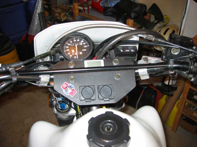
Here is a picture of the compleated panel. I started out by making a cardboard template to figure out the shape I wanted. The heated grips and the left accesory socket are wired to the ignition. The right socket is wired to always provide power. The voltage meter is wired to the left accesory socket so it only reads with the key on.
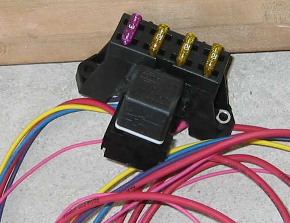
This is the heart of the setup. It's a Painless Wiring 3 circuit waterproof circuit isolator. P/N 70203. It actually really was rather painless to install.
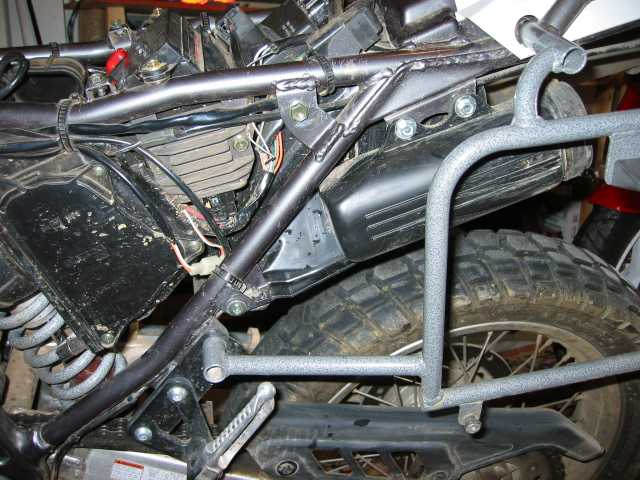
After looking around the bike I decieded to mount the fuse block infront of the toolkit box on the left side of the bike.
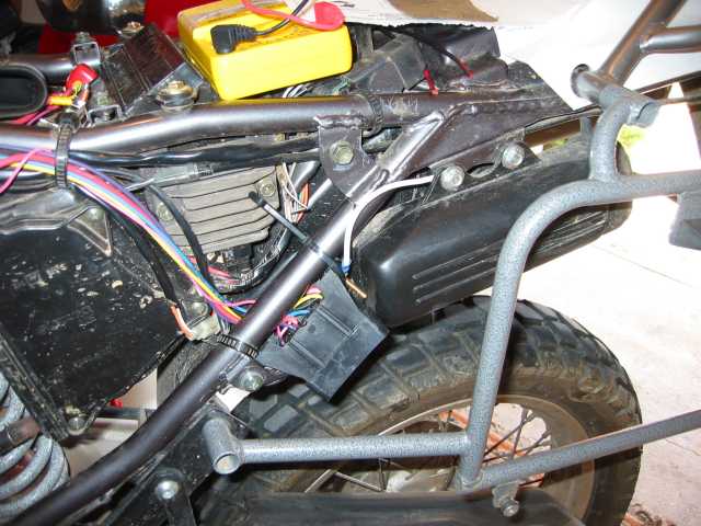
I had to trim a bit of the rear fender but it fit rather snugly and routed the wires along the left side of the frame up to the steering head.